


A low overhead flow-holding algorithm in software-defined networks【2】
2.2. Holding more flows
If the network wants to hold more flows, the effective way is to aggregate the flow sets to improve the utilization of the flow table entries. We introduce the flow sets to path aggregation and path ID assignment methods based on the coincidence degree of flows
on the forwarding path [6]. KSGT achieves flow-level explicit path control by encapsulating MPLS labels to packets, which can com- press a large number of flows to a small number of routing entries in some switches on the forwarding path. Furthermore, KSGT can pre-install the flow entries through the controller’s pre-calculated according to the path ID.
2.2.1. Flow sets to path aggregation
Some works [12,14] propose the segment routing architecture and they detail the operation mechanism of segment routing in data centers and wide area networks. All these papers do not con- sider how to realize flow sets to path aggregation, and how to un- date the flow ID when new flows arrived. We propose a generic flows aggregation method based on segment routing. Moreover, [6] shows that DCNs do not intend to use all possible paths but a set of desired paths. While there also exist key nodes in the WAN that most of the traffic pass through them [20,21]. Thus, we improve the KSGT to select the least intermediate nodes to achieve maximum flow aggregation by encapsulating MPLS labels.
As Fig. 3(a) shows, we select some key nodes M in the network, while the flows come from source node S to destination nodes D must pass through at least one of them. The controller distributes the IDs to the flows form S to M and form M to D. According to the path ID the SDN switch encapsulates MPLS labels to the flows to indicate the switch ports of forwarding path.
2.2.2. Holding more flows
KSGT can reduce a large number of flow table entries by reusing the flow entries to encapsulate and decapsulate the MPLS labels. Our model in Section 3 uses a cost function to balance the flow table entries of different switches. Hence, KSGT can accommodate more flows even if the capacity of TCAMs in switches is limited.
The general packetout message of SDN is to install flow en- tries in all switches of forwarding path. But we just select a few switches to install flow entries by encapsulating the MPLS labels. It can save TCAM resources by reducing a large number of flow table entries. Moreover, unlike traditional MPLS technology, there is no need to maintain path state in forwarding path except on the ingress node, because packets are now routed based on the list of labels they carry [11]. The flow table compression based on path ID reduces the flow table entries. We reused the flow entries by encapsulating the MPLS labels for the flows of those forwarding paths are overlap. Moreover, we also reused the flow entries to pop up the MPLS labels as the switch port number of the forwarding path for the flows. In Fig. 3(b), if the flows come from source switches S through intermediate switch M1 to the destination D1, we can only install one flow entry in the switch M1 for all flows to encapsulate MPLS labels. Meanwhile, we only need to install one flow entry for each switch from M1 to D1 to pop MPLS labels as the forwarding port.

3 Problem Formulation
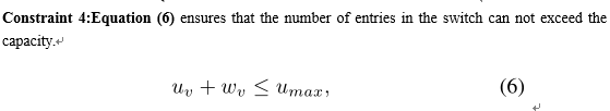
We formulate the reactive flow entry placement problem with the objective of achieving low overhead and more flows hold by properly selecting the placement and the number of contact switches. Let G = (V, E) be a network, where V is the set of nodes, and E is the set of links. Let $F$ denote the set of traffic flows. We use v to represent a node in the network, f to represent a flow in the network. Let r_f denote the arrival rate of flow f, and u_{max} be the flow table capacity of a SDN switch. We use u_v to denote the number of entries in the node v that have been installed before the arrival of the flows, w_v to denote the number of entries to be installed in the node v by controller for all flows. The full list of notations is shown in Table \ref{table:1}..
3.1 Constraints
in the network. Let r denote the arrival rate of flow f, and umax be the flow table capacity of a SDN switch. We use uv to denote the number of entries in the node v which have been installed before the arrival of the new flows, and wv to denote the number of entries to be installed in the node v by the controller for all flows. The full list of notations is shown in Table 1.
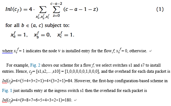
Definition 1 (Overhead). The MPLS labels cannot be regarded as payload. We define the overhead as Inl(cf) since the flow f is encapsulated with MPLS labels to carry the routing information [22,23]. The size of each MPLS label is 4 bytes, so the overhead for flow f can be formulated as:
Definition 2 (Border load). We define border load φ as the tolerable overhead proportion of each packet in the network.
The smallest data packet size is 46 bytes in the network, but the size of each MPLS label is 4 bytes [23]. In Fig. 1, if it just installs entry at the flow’s ingress switch, the size of MPLS labels is 4 × 9 = 36 bytes for each packet, and the overhead on the link between s1 and s2 is more than 12% of total load for these packets whose sizes are less than 300 bytes. Note that there are many different network packets whose sizes are between 100 bytes and 300 bytes according to the statistics in [17]. The longer the forwarding path is or the smaller the packet size is, the larger the overhead becomes [18]. So we must select some other nodes to install en- tries to reduce the overhead instead of just installing entries in the ingress switch. Hence, we define the border load ratio φ for each packet in the network to limit the overhead [24].
According to the measurement method in [25], we can suppose an observation window contains S packets at time t. The average packet size at time t is defined as

 |  |
分享让更多人看到 
推荐阅读
传媒推荐
 @媒体人,新闻报道别任性
 网站运营者 这些"红线"不能踩!
 一图纵览中国网络视听行业
相关新闻
人民日报社概况 | 关于人民网 | 报社招聘 | 招聘英才 | 广告服务 | 合作加盟 | 供稿服务 | 数据服务 | 网站声明 | 网站律师 | 信息保护 | 联系我们
服务邮箱:kf@people.cn 违法和不良信息举报电话:010-65363263 举报邮箱:jubao@people.cn
互联网新闻信息服务许可证10120170001 | 增值电信业务经营许可证B1-20060139
广播电视节目制作经营许可证(广媒)字第172号 | 互联网药品信息服务资格证书(京)-非经营性-2016-0098
信息网络传播视听节目许可证0104065 | 网络文化经营许可证 京网文[2020]5494-1075号 | 网络出版服务许可证(京)字121号 | 京ICP证000006号 | 京公网安备11000002000008号
人 民 网 版 权 所 有 ,未 经 书 面 授 权 禁 止 使 用
Copyright © 1997-2021 by www.people.com.cn. all rights reserved


-
评论

-
关注
微信微博快手
 第一时间为您推送权威资讯
 报道全球 传播中国
 关注人民网,传播正能量
