�ֻ�������
 ����������
Abstract:Today��s system-on-chip and distributed systems are commonly equipped with multiple clocks. The key challenges in designing such systems are (1) how to model multi-clocked local synchronous component, local asynchronous component, and asynchronous communication among components in a single framework, (2) how to ensure the correctness of model, and keep consistency between the model and the implementation of real system. In this paper, we propose a novel computation model named GalsBlock for the design of multi-clocked embedded system with both synchronous and asynchronous components. The computation model consists of several hierarchical compound and atom blocks communicating with data port connections. Each atom block can be refined as parallel mealy automata. The unified operational semantic and formal semantic are defined, which can be used for simulation and verification, respectively. Then, we can generate efficient VHDL code from the validated model. The size of the generated code is reduced by up to 40% compared to simulink VHDL code generator of Stateflow for a function that can be modeled by both Galsblock and Stateflow. We have developed the graphical modeling, simulation, verification, and code generation toolkit to support the computation model, and applied them in the design of a sub-system used in the train communication control according to the standard IEC-61375. Two critical bugs in the standard are detected in the model validation process, and the automatically generated sub-system according to the revised model is now used in real subway control.
key words: Embedded System, Formal Model of Computation, Simulation and Verification, Code Generation
1 Introduction
Embedded systems are being widely used and are vital to many critical complex applications. They usually involve concurrent behaviors with different local control clocks, which leads to several challenges for the traditional computation model. The first challenge that the computation model faces is the modeling capability that how to evaluate the behavior of the local synchronous component, asynchronous component and their communications in a single model. For synchronous components, operations are coordinated under the centralized control of a fixed-rate clock signal or several clocks. For asynchronous components, in contrast, have no global clock. Instead, they operate under distributed control, producing outputs in response to input changes. The asynchronous communication among these components should be synchronized with all corresponding clocks. The second challenge focuses on the analytical capability, including how to ensure the correctness of the model, and keep the consistency between the model and the implementation.
A lot of researchers have made many efforts at the computation models [2], [17], but there are not practical solution for multi-clocked embedded systems. In this paper, we present an automaton [24] and block diagram [26] based computation model named GalsBlock to address the challenges in modeling, validation and implementation of multi-clocked embedded system with mixed synchronous and asynchronous components. In the proposed computation model, a system is modeled as a combination network of compound and atom blocks communicating through data ports connections. The compound block can be refined by some other sub-compound and sub-atom blocks hierarchically, and the atom block is refined by some parallel mealy automata with optional clocks. Despite the regular state transitions, we allow users to append complex actions and priority on the transition to enhance the modeling ability. The atom block with clock is used to capture the behavior of synchronous component, and the block without clock is used to capture the behavior of asynchronous component. The connection among data ports attached on different blocks is used to capture the asynchronous communication, and the expression appended on the connection is used to facilitate the modeling of data-oriented behaviors. We use all local clocks and signal dependencies to give a topological sort of all atom block computations to solve the indeterminacy caused by parallel execution. We develop the toolkit to support the computation model. Then, the design and implementation of complex embedded systems can be simplified to three steps. First, we can build the graphic model of GalsBlock based on the system requirement and function descriptions. Then, the model can be simulated and verified for all kinds of properties derived from the requirements. If properties are not satisfied, we should return back to the modeling stage to find bugs in the model. This helps us find problems in the early stage of system design. Finally, after all properties are satisfied, we can generate the executable implementation from the validated model automatically. This is efficient because coding with underlying programming languages such as VHDL and C according to the requirements directly is more difficult than building the abstract level GalsBlock model. Furthermore, simulation of VHDL and C programs needs more efforts to write test benches, and the verification is even harder with more limitations. We apply GalsBlock and the toolkit to the design of a multifunction vehicle bus control system of train communication network according to the standard IEC 61375. Two critical bugs in the standard are detected during the model validation process. Two bugs have been certified and the automatically generated sub-system is now deployed in real subway control system.
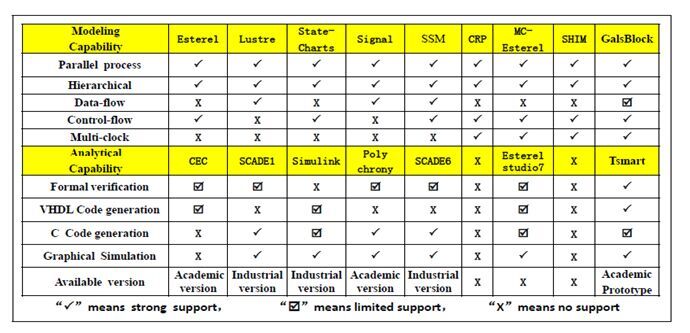
Fig. 1. The modeling capabilities of the system level modeling languages based on formal computation model and the corresponding available tools supporting the analytical capabilities.
2 Related Work
A large body of work has been dedicated to facilitate the design of embedded systems. In the literature, the formal computation model based approach is appealing because it provides a unified basis for formal analysis to achieve expected correctness. Traditionally, embedded systems are supposed to be controlled by a single synchronous clock, and the class of formal computation modeling languages constructed on this hypothesis mainly contains Esterel [6], Lustre [13], Statecharts [15] and Signal [22]. Those modeling languages are the basis for synchronous system design but are not fit for the system controlled by multiple clocks with both synchronous and asynchronous components.
Embedded systems on the current market are more and more complex that the synchronous hypothesis is not valid. Most systems consist of hundreds of components, which can be controlled by many local clocks. The formal computation modeling languages for multi-clocked systems mainly contain CRP [4], MC-Esterel [5], and SHIM [12]. CRP combines the synchronous reactive model of Esterel [21] with the asynchronous coupling of CSP [18] to offer a mathematically elegant framework. Locally synchronous Esterel modules communicate through rendezvous channels. The problem is that it is hard to support data-driven operations and rendezvous protocol through asynchronous coordinators. Its variants such as CRSM, ECRSM [23] have similar limitations. MC-Esterel is specifically developed for the design of multi-clocked digital systems. The designer is responsible for creating communication mechanisms among different clock domains. Esterel modules need explicit clocks and a designer has to construct underlying synchronizers to guarantee the synchronization among these modules. While MC-Esterel provides a powerful mechanism for modeling asynchronous and multi-rate systems, the problem is that a designer has to work at a relatively underlying level and the productivity is limited. In addition, its support for data-driven operations is quite limited due to its reliance on Esterel. The main idea of SHIM is that both hardware and software functions are written as C-like functions and the communication between these asynchronous objects is mapped to a restricted Kahn Process Network. The major limitation of SHIM is the lack of support for modeling reactivity and synchrony behaviors.
Based on the above formal computation modeling languages, there are many corresponding toolkits. For traditional synchronous computation modeling languages, the most famous tool is SCADE [9]. The computation model used in SCADE combines Lustre and Esterel. The constructed model can be simulated, verified and used to generate C code for embedded software implementation. With strong modeling ability, the properties can be verified on the model are limited to certain types such as deadlock. Furthermore, the support for hardware processor implementation such as VHDL code is none. For multi-clocked systems, Esterel studio v7 [3] supports the design of digital systems based on MC-esterel. But the code generation capacity for it is limited, many basic constructs are not supported, and the simulation is not visual. The verification tool Xeve only supports pure signal, and cannot deal with valued signals and variables. Furthermore, we cannot find an alive version for use anymore. Ptolemy [7] supports modeling, and simulation of mixed synchronous and asynchronous systems. A major problem area being addressed is the use of heterogeneous mixtures of computation models (e.g., asynchronous discrete event and synchronous dataflow) in hierarchical way. The inner model will lose some original properties when adjusting to the outer model of computation. Furthermore, it is primarily used as a simulation environment and cannot be verified and synthesized. Simulink [9] also has the same disadvantage of no formal semantic. Furthermore, the operational semantic of the parallel execution of stateflow [14] is too complex and dependent on the relative position of the module. The VHDL code generation algorithm is not efficient, neither. Besides these environment, some translation based frameworks are also proposed to solve the analysis of multi-clocked systems. For example, F. Doucet et al. [11] use a mixture of synchronous descriptions in Signal and asynchronous descriptions in Promela, and provide a translation from Signal modules to Promela processes. Each clock domain is described by a Signal module, and communication between two clock domains is described by Promela channel. The underlying deficiencies of these modeling languages are actually prevalent in those traditionally modeling and validation frameworks as presented in Fig 1, which motivates our work. The proposed GalsBlock has clear operational and formal semantics, as well as complete toolkit for hierarchical graphical modeling, validation and implementation.
3 GALSBLOCK
In this section, we introduce the computation model GalsBlock, including the graphical elements, operational semantic for simulation, and the formal semantic for verification.
3.1 GalsBlock Computation Model
The example in Fig 2 illustrates the features of GalsBlock. At the top level, the compound block CompoundTop consists of two sub-blocks (compound block Compound1 and atom block Atom1). The compound block does not do computation, just presents the hierarchical decomposition of system structure, and the data flow path among the structured blocks. The clock attached on the compound block does not plays a part, and just provides a virtual interface for the control clocks of its inner atom blocks. For example, the frequencies of virtual clock CLK1 and real clock CLK2 are derived from the virtual clock CLK0, where the derived rules such as double and triple frequency multiplication can be configured according to different requirements. The black dot attached on the right side of each block is used to denote the output data port, while the blue dot on the left side is used for the input data port. The input data ports of CompoundTop can be connected to the input ports of the two sub-blocks (b -> g, a -> c), and the output ports of the sub-blocks can be connected to the both input and output data ports of other blocks (e -> f, h -> i). The expression on the connection from port b to port g facilitates the data-oriented behavior modeling.
The asynchronous communication denoted by connection between two ports is realized through asynchronous channel. Once the atom block finishes the computation at the beginning of the local control clock, the data from the output data port will flow through connections to the sink port, until the arrival of the input port of another atom block or the output port of the top block. The atom block on which the sink port is attached will read the value for computation at the beginning of its local clock. In case of conflicts of read-write operation during parallel execution, the old value will be read according to propagation delay. For example, block Atom2 will update the output port m when the computation finishes at the periodical beginning of clock CLK3, and the updated value will flow through connection (m -> o) until the connected input ports of another atom block. Because block Atom3 is asynchronous, it will do computation and update the output data port q immediately. Then, the updated values will flow through connections (q -> e, e ->f) until the connected input ports of another atom block Atom1. At the next periodical beginning of clock CLK2, block Atom1 will read the updated value for computation. If the periodical beginning of clock CLK3 happens to be the same as clock CLK2, the parallel operation will lead to conflict of read-write operation. The conflict can be solved by the delay of computation and signal flow in real world. Based on this fact, we embed the delay into the semantics that read operation is prior to write operation when the conflict caused by same frequency of clocks happens.
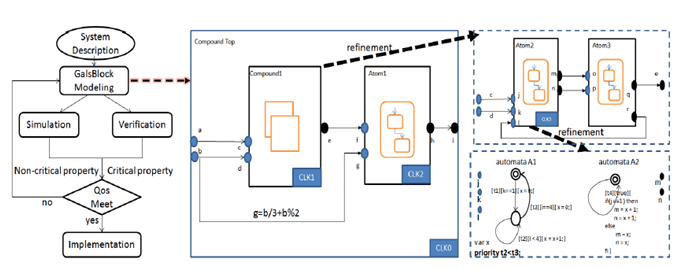
Fig. 2. The left side is the system design flow based on the computation model GalsBlock. The right side is an example of GalsBlock, including the graphical elements of compound and atom blocks. The top model consists of compound block Compound1 and atom block Aotm1. The compound1 is refined as atom blocks Atom2(synchronous) and Atom3(asynchronous). The Atom2 is refined as two automata running in parallel.
Besides the solution for the read-write operation conflict, we release certain types of cycle restriction in the model. The cycle in which there is a synchronous atom block is broken by the inner data communication principle presented above. For example, the compound block Compound1 which is refined as two atom blocks (Atom2 and Atom3) contains a direct cycle. The connection from port r to port l results a cycle among the two atom blocks. If the output port m of block Atom2 is updated when the computation finishes at a periodical beginning of CLK3, the value will flow through connection (m -> o). Because block Atom3 is asynchronous, it will perform computation and update the output data port q and r immediately on the changes of its input ports. The updated value of port r will be passed to port l of block Atom2 instantaneously. But this will not lead to infinite computation cycle, because block Atom3 will not read the updated value for computation until the next periodical beginning of clock CLK2. Remind that the cycle in which all elements are the asynchronous atom block will lead to timing paradox.
With the hierarchical structure and dataflow are presented in the compound block, system behaviors are described by parallel automata in the atom block. For example, the atom block Atom2 is refined as two automata controlled by clock CLK3, with a local shared variable and a transition priority. For synchronous atom block, the inner automata are controlled by the same local clock. At each periodical beginning of the clock, each automaton is allowed to take a step of transition or stay in the current state. Each transition consists of three parts: name, guard, and action. The priority is defined on the name of two transitions in a single automaton in case that both transitions meet their guards. The action supports some basic control structure such as IF ELSE statement. All statements and guards are defined on the ports and local variables. For parallel execution of multiple automata, there will also be conflicts on read-write operation. Each local variable and output data port can be written by one automaton for only one time, and the write operation is prior to the read operation. When all automata finish the computation, values of output ports and local variables will be updated, and passed through the connection to the endpoint which is the input port of another atom block or the output data port of the top block. For asynchronous block, the inner automata are triggered by the changes of the input data ports, and may take several transitions from the current state until no guard is satisfied.
3.2 Operational Semantic of GalsBlock
The operational semantic of GalsBlock is defined on configuration. A configuration is a maximal set of states that the system could be in simultaneously. Any subset of states is not a legal configuration. Let B be the top block associated with a GalsBlock, consisting of several synchronous and asynchronous atom blocks bi. A legal configuration C for GalsBlock satisfies: for each atom block bi contained in B and each automaton ci directly contained in bi, C must contain exactly one state directly contained in ci. Then, the operational semantic can be transferred to the configuration computation.
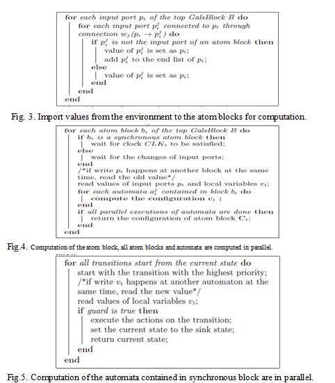
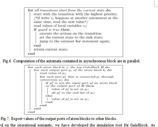
Because the compound block just presents the decomposition of the system structure and does not do computation, hence, the computation of GalsBlock relies on the computation of its atom blocks. The computation of GalsBlock can be divided into three macro steps: (1) Import values from the environment to input ports of the top model continuously, and passes those updated values to the input ports of atom blocks through connections; (2) Atom blocks will read updated values of input ports for configuration computation on the periodical beginning of each local control clock with predefined priority rules in section 3.1; (3) When an atom block finishes the computation, export all output ports to the connected compound and atom blocks. The algorithm implementation of the three steps are described below. Notice that the second step for configuration computation is decomposed hierarchically, and the computation mechanism is different for synchronous and asynchronous blocks.
For the first step presented in the Fig 3, the top model imports inputs from the environment continuously. It should get the value and pass the value through connections until the endpoint arrives, which is the input data port of an atom block. Note that the value may flow through some compound blocks before arriving at the endpoint. For the second step, the computation of GalsBlock has been divided into the computation of atom block and automata hierarchically. The automata computation contained in synchronous atom block is triggered by the local clock, and all automata are allowed to take at most one transition only. While for the asynchronous atom block, the automata computation is triggered by the changes of input data ports, and all automata can take different number of transitions until no guard is satisfied. The asynchronous block reads the updated values immediately, while the synchronous block reads the values according to the local clock. Then, the parallel automata in each block will compute the next state and the values of the output ports and shared variables with priority in consideration. Each automaton contained in the synchronous block is allowed to take only one step, while the automaton contained in the asynchronous block is allowed to take several steps until no guard is satisfied. After the recursive execution finished, the configuration as well as the values of output ports will be returned. The details are described in the Fig 4, 5 and 6. For the third step presented in the Fig 7, each atom block updates the value of the shared variables and exports output ports. The value of the updated output ports should be passed through connections until the endpoint arrives, which are the input ports of an atom block, or the output ports of the top block B.
Based on the operational semantic, we have developed the simulation tool for GalsBlock. As described in the experiment section, the model can be simulated step by step, and the user can capture the state of each atom block and the value of each output port and local variable for each configuration. This facilitates the designer to ensure the correctness that the behavior of the model maps the systems requirements to be implemented. Through the simulation tool, most of the functional requirements can be checked on the model. While coding with the underlying programming language such as VHDL and C according to the requirements directly is more difficult than building GalsBlock model. Furthermore, the simulation of VHDL and C programs needs more efforts to write test benches.
3.3 Formal Semantic of GalsBlock
For the formal semantic definition of GalsBlock, there are two methods for choice. The first is to translate GalsBlock to an existing model that has formal semantic. Then, the translation of GalsBlock can be interpreted and verified directly based on the supporting tools of the target model. The second is to define the basic formal semantic by its equivalent labeled transition system [8], which is the basis for verification. The labeled transition system is constructed bottom-up, by starting from the lowest hierarchical level parallel automaton Ci of each atom block bi and moving upwards to the top level block B through combination.
Definition 1: A chart Ci in an synchronous atom block is a tuple () , where L is a set of locations,L is the initial location, V is a set of parametersinherited from the local variables, input ports, and output ports of the atom block, A is a set of actions , E is a set of edges between locations with the action and guard, G(V) is the set of guard on parameters, P is the set of priority valuation function on edges that may take simultaneously, and T is the synchronous trigger signal.
Let be a chart contained in the synchronous atom block. U is a set of parameter valuation function from the parameters to t boolean or integer value. Then, the semantic of the chart is defined as:
Property 1: The semantic of this chart Ci can be defined as a labeled transition system��where S is the set of configuration ,is the initial configuration, and is the transition relation such that:
, if there is a transition,, when the trigger T happens.
, if there is no transition,, when the trigger T happens.
An atom synchronous block may consist of several charts over a common set of parameters and trigger signal. The atom block performs reactive actions on the trigger signal: read value of input ports and local variables, do some computation, and update the value of output ports and the local variables. Upon the computation, these charts run in parallel. Then, the semantic of the atom block can be defined as follow:
Definition 2: An atom block Bi is a tuple,, where I is a set of input ports, O is a set of output ports , V is a set of local variables , C is a set of charts , and T is the synchronous trigger signal.
Let be an atom block, consisting of n charts, The chart Ci equals, where. Then, the location set for the atom block is defined as, and equals. The action set is defined as. For chart is a set of parameter valuation function from the parameters to the bool or integer value. Then, for the atom block, is defined as, and equals. Then, the semantic of the atom block is defined as follow:
Property 2: The semantic of this atom block can be defined as a labeled transition system based on the semantic of chart, where S is the set of configuration is the initial configuration, and equals. Transition is the transition relation such that:
Each chart in the synchronous atom block should take one and only one action in a computation cycle, staying in the current state or jumping into the sink state. This is the key difference between parallel computation of GalsBlock and the computation of timed automata. In timed automata, the network of automata does not need to be synchronized. Each automaton can take any transitions that satisfy the condition, while each chart in GalsBlock is allowed to take only one transition. In the same way, we can construct the labelled transition system for the asynchronous system.
The compound block may consist of several synchronous and asynchronous atom blocks with many input ports and output ports connection. After each computation of the atom block, the value of the output may flow to input port of another block. The compound block does not do computation, just some connection of ports. When we at the module, it has nothing to do with the semantic. And the semantic of the GalsBlock language can be reduced to the parallel execution of all atom blocks.
Definition 3: The top block M is a tuple, where I is a set of input ports, is a set of output ports, B is a set of atom blocks, W is a set of connections, and T is the set of synchronous trigger signals.
Let be the top block, consisting of n atom blocks. The block Bi equals. Then, the location set is defined as, andequals. The action set is defined as. For atom block is a set of parameter valuation function vector from the parameters to boolean or integer value. Then, for the top block, is defined as,equals . Then, the semantic of model is defined as follow:
Theorem 1: The semantic of this top block is defined as a labeled transition systembased on the semantic of atom block, where S is the set of configuration is the initial configuration. Transition is the transition relation such that, when a trigger T happens, where,, and ,, and is defined in property 2.
Then, we can formalize decision problems in GalsBlock in the same way as timed automata [1]. Based on the semantic of the labeled transition system, the verification team in our lab has developed a verification tool [16] 8 for the GalsBlock model. Then, several safety critical properties can be verified directly, and the incompleteness of simulation can be overcome through this way. As presented in experiment results, when design the train control system according to the standard, some critical bugs are detected during the verification based on the labeled transition system.
4 Model Implementation
In this section, we concentrate on the automatic implementation, where another strength of GalsBlock is demonstrated. Generally speaking, GalsBlock does not need special programming language for implementation. However, it is desirable to map the hierarchical structure�� parallel processing��synchronous and asynchronous behavior descriptions to a corresponding programming language. The consistency between GalsBlock and the implementation of real system can be acquired better.
Following the above principles, we choose VHDL code for the implementation of GalsBlock. Because VHDL provides good way to describe both synchronous behavior and asynchronous behavior, although it is not easy to use for software engineers and for verification. The system implementation by programming VHDL code directly is complex and intuitionistic. We will overcome this gap by defining some mapping mechanism to derive the underlying VHDL code from the abstract GalsBlock model. Furthermore, the VHDL code is generated in the manner of three stages, which is cumbersome to write but is the best organization of VHDL code description. Each atom block can be mapped to an entity description of VHDL code. The parallel automata can be mapped to process description contained in VHDL entity. The clock used to control the synchronous block can be mapped to the process trigger signal of VHDL code. The compound block and connections can be mapped to component map of VHDL code. When the user chooses the top block, the kernel should generate a set of VHDL codes for the computation of all atom blocks, and the hierarchical relation contained in the compound block. The details of the macro generation steps are described below.
First, let us see the code generation of the synchronous atom block presented in Fig 8. The atom block contains priorities, input ports, output ports, shared variables, and some parallel automata to describe the behavior. We should process these elements into an equivalent VHDL entity. The first step is to generate the ENTITY definition of a VHDL module for the input ports and output ports. Because we support boolean and integer in GalsBlock, we need to change the boolean to std_logic in VHDL for more efficient synthesis. Besides, we also need to add the clock signal CLK and system reset signal RST into the interface definition of the ENTITY. The second step is to generate a signal for each shared variable and automaton, which is used for behaviors description. For each automaton, we need to all a type definition for the state and generate the three-stage code. The first stage is the update of state, the second is the state transition, and the third is the output computation. The second and third stage can be captured by the CASE statement of VHDL, and the priority of different transitions can be captured by the IF ELSE statements inside a branch of WHEN. The code generation algorithm for the asynchronous atom block is the same, except that the sensitive signals of process are changed to the input ports with the clock signal.

Then, let us see the code generation of the compound block presented in Fig 9. The first step is to generate the ENTITY definition, in the same way as the atom block described above. The second step is to generate the COMPONENT instance for each contained block, and some temporary signals for connection. We need to declare the instance for all blocks contained in the selected compound block. There are two kinds of connections. The first is the connection between two inner blocks, and the second is the connection between the compound block and the inner block. For the first, we need to generate some temporary signals for component port map. We extend the name of the right port of the connection to the temporary signal. The third step is to initiate the signal connection for each COMPONENT instance according to the connection. If the port of the component is connected to a inner port, it is mapped to the generated temporary signal. Otherwise, it is mapped to the original port signal. The data-oriented behaviors appended on the ports connection are transferred to the signal update of VHDL statements.
Based on code generation algorithms, blocks can be chosen to be implemented, and get the VHDL code automatically. We have implemented the code generation tool. Furthermore, for a function that can be modeled by both Galsblock and Stateflow, the size of the generated code is reduced by up to 40% compared to simulink VHDL code generator of Stateflow. With the help of Xilinx ISE toolkit, we can also simulate the generated VHDL code, and compare the result of the code simulation with the result of the GalsBlock model simulation. We have do large amounts of simulation comparisons to prove the consistency between the model and the generated code. Furthermore, the generated code can be synthesized and loaded into the FPGA processor to run directly. This facilitate the designer to ensure the consistency of the model and the implemented system.
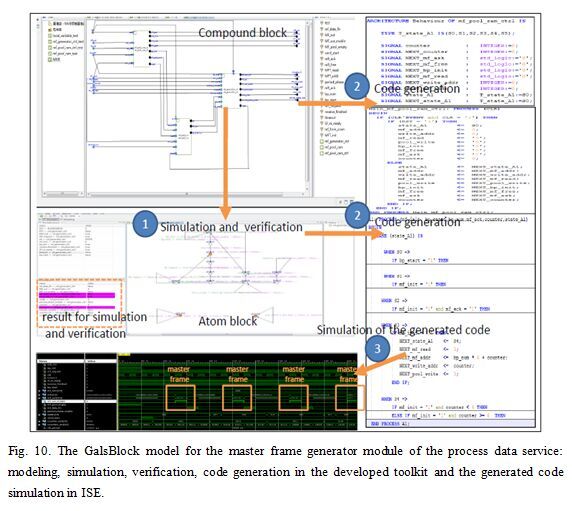
Fig. 10. The GalsBlock model for the master frame generator module of the process data service: modeling, simulation, verification, code generation in the developed toolkit and the generated code simulation in ISE.
5 Experiment Results
We have implemented the graphical modeling, simulation, verification and code generation toolkit to support the GalsBlock model of computation. Then, apply the tool to a real sub-system design of the train communication control system. Traditionally, the company such as Duagon and China North Railway develop the system by writing VHDL codes directly according to the description of IEC 61375 [10], which is hard working and the code reliability cannot be guaranteed. For example, we have found some deadlocks in the VHDL codes of China North Railway. The system consists of many multifunction vehicle bus (MVB) controllers interconnecting devices within a vehicle. MVB controller mainly provides time-critical process data communication and delay-tolerant information data communication. The communication is controlled by one master, which controls the sending of all data frames on the link layer bus. The master broadcasts a master frame, which carries the identifier for a process data frame. The device which sources this process data responds by broadcasting a slave frame. In order to accomplish this function, MVB controller needs a master frame sender control module and a process data response control module. In each basic period, the sender module reads 8 master frames from the memory and sends them onto the link layer, and the corresponding controller will read process data from the memory and broadcast them onto the link layer for each master frame. The main modules are designed, validated, and generated automatically in GalsBlock, according to the description of the standard.
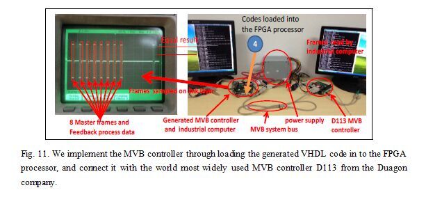
Fig. 11. We implement the MVB controller through loading the generated VHDL code in to the FPGA processor, and connect it with the world most widely used MVB controller D113 from the Duagon company.
We use a compound block mf generator contained in the master frame sender control module to demonstrate the tool support of GalsBlock for system design. It consists of three synchronous atom blocks (mf-generator-ctrl, mf-pool-ram, mf-pool-ram), and is used to generate the master frame to be sent. It will ask for the use of memory, and read the master data. The data read procedure is controlled by the block mf-pool-ram-ctrl. The master frames read from the memory are stored in the block mf-pool -ram, and can be sent through the block mf-generator-ctrl. We build these atom blocks first, and drag them into the interface and connect those corresponding ports. As presented in Fig 10, the atom block mf-generator-ctrl contains three parallel automata. The first is for the main control logic that reads the master from the pool ram and sends it to the link layer, and the other two are for the aided counter. For each computation, we can input the values of input ports. The resulted values of the output ports and shared variables, and the current state of the automata are highlighted in the graphical interface. We can also input some computation tree logic (CTL) expressions, and the results of the developed verification tool Beagle [16] are highlighted. If the model simulation or verification works as expected, we can generate VHDL code for this compound block directly. Four VHDL documents consisting of 945 lines of VHDL codes are generated, one document for the architectural description of the compound block, and three for the behavioral description of the atom blocks. The size of VHDL code for atom block mf �Cgenerator-ctrl is 359 lines about 7 KB. If we use stateflow to model this function and generate the code by simulink, the size is 602 lines about 12 KB, although the number of states is the same for the two models. The comparison for other two atom blocks is almost the same. The VHDL code can be simulated in the ISE of xilinx, with some handwrite test bench case. The waveform of simulation shows that the generated codes work well and can generate 8 master frames in correct timing sequence. We compare the output result of the code simulation with the result of the GalsBlock model simulation for each computation step.
For process data communication service of MVB controller, we need six blocks to send the master frame to the data link layer: the kernel compound block mf generator, the synchronous atom block macro timer, tm-access-ctl, mf-send-ctl and mux-in, and the asynchronous atom block mem-store. The macro timer is used to start the periodical phase with the output port out bp-start per 1ms. The output port bp-num is used to determine the address of the master frame in this period. The memory data access is controlled by the tm-access-ctrl block. The mf-send-ctrl block is used to control the sending of the generated master frame from the atom block mf generator ctrl. The atom block mux in transmits the master frame data to the sender of the system. Also, we need another four blocks to response the feedback process data to data link layer: the synchronous atom block receiver-controller used to distinguish master frame or process data frame, sink-source-controller used to distinguish the master frame should be responded by this device or not, and data-send-timer used to decide when to read the process data from tm-access-ctl and send it onto the link layer. For information data communication service, we need 9 blocks to accomplish the task. Firstly, we build all blocks strictly according to the algorithm and pseudo code descriptions in the standard IEC 61375. Due to limited space, all blocks can be found on the website [25]. Then, we do some simulations and verifications through the developed toolkit. Unfortunately, the first version of the constructed model cannot accomplish the information data communication service. Through artificial analysis, we locate the problem in the atom block send-device-status. We find that the guard for information retransmission function is implemented as (expected < NK number<=send-not-yet) according to the pesudo code description in Table 33 of IEC 61375. We find the guard fails to cover all the situations that needs retransmission, and should be changed to (expected <=NK number<= send-not -yet). Another bug in the algorithm description in the Table 35 of IEC 61375 is also detected. In order to check the authenticity of detected bugs by our tool, we transform GalsBlock to timed automata through the method presented in [19], and the detail verification proofs by Uppaal for the bugs in the standard are presented in our previous work [20]. The bugs have been certified through theoretical analysis and our engineering practice, and proposed to the standard organization. The revised GalsBlock model passes the simulation and verification.
Then, we generate the VHDL code from the revised GalsBlock model automatically, and load the generated 9845 lines of VHDL codes into the FPGA processor of MVB controller. The world most widely used MVB controller D113 from Duagon Company are connected to test the reliability of the generated system through the system bus as presented in Fig 11. The implemented system is embedded into industrial computer to get some instructions from the keyboard, such as communication start. We use the application running on the industrial computer to monitor the communication. Furthermore, we also use oscilloscope to sample the data from the serial port that connected to the MVB bus. Both methods shows that the master frame and the feedback process data is sent correctly. Now, the system has been deployed on the real control system of subway.
6 Conclusion
In this paper, we present a synchronous and asynchronous cooperation computation model for embedded system design. The hierarchical blocks and the port connection among these blocks present the decomposition structural and the signal flow of the system clearly. The parallel automata in the atom block controlled by different clocks describe the control logic and computation of each function. The operational semantic based on the execution logic of real systems and the formal semantic based on the labelled transition system facilitate the designer to do some simulation and verification in the early stage of system engineering. The implementation of GalsBlock is accomplished automatically, the generated VHDL code can be synthesized and loaded into FPGA processor directly. We have developed the modeling, simulation, verification and code generation toolkit to support GalsBlock. We apply it to the design and automatically implementation of a subsystem in train communication control system, and the generated sub-system is now deployed in a real subway. In the future, we focus on the formal verification of the generated code and the code generator.
REFERENCES
[1] R. Alur. Timed automata. In Computer Aided Verification, pages 8�C22. Springer, 1999.
[2] F. Balarin, Y. Watanabe, H. Hsieh, L. Lavagno, C. Passerone, and A. Sangiovanni-Vincentelli. Metropolis: An integrated electronic system design environment. IEEE transaction on Computer, 36(4):45�C52, 2003.
[3] G. Berry. Circuit design and verication with esterel v7 and esterel studio. In High Level Design Validation and Test Workshop, 2007. HLVDT 2007. IEEE International, pages 133�C136. IEEE, 2007.
[4] G. Berry, S. Ramesh, R. Shyamasundar, et al. Communicating reactive processes. In Proceedings of the ACM SIGPLAN-SIGACT symposium on POPL, volume 20, pages 85�C98. ACM, 1993.
[5] G. Berry and E. Sentovich. Multiclock esterel. Proceedings of the Correct Hardware Design and Verification Methods, pages 110�C125, 2001.
[6] F. Boussinot and R. De Simone. The esterel language. Proceedings of the IEEE, 79(9):1293�C1304, 1991.
[7] C. Brooks, E. A. Lee, and S. Tripakis. Exploring models of computation with ptolemy ii. In 2010 IEEE/ACM/IFIP International Conference on Hardware/Software Codesign and System Synthesis (CODES+ISSS), pages 331�C332. IEEE, 2010.
[8] M. Bundgaard. Labelled transition system.
[9] P. Caspi, A. Curic, A. Maignan, C. Sofronis, S. Tripakis, and P. Niebert. From simulink to scade/lustre to tta: a layered approach for distributed embedded applications. In ACM Sigplan Notices, volume 38, pages 153�C162. ACM, 2003.
[10] I. E. Commission et al. Iec 61375-1. Train Communication Network, 2011.
[11] F. Doucet, M. Menarini, I. H. Kr�� uger, R. Gupta, and J.-P. Talpin. A verification approach for gals integration of synchronous components. Theoretical Computer Science, 146(2):105�C131, 2006.
[12] S. Edwards and O. Tardieu. Shim: A deterministic model for heterogeneous embedded systems. IEEE Transactions on Very Large Scale Integration Systems, 14(8):854�C867, 2006.
[13] N. Halbwachs, F. Lagnier, and C. Ratel. Programming and verifying real-time systems by means of the synchronous data-flow language lustre. Software Engineering, IEEE Transactions on, 18(9):785�C793, 1992.
[14] G. Hamon and J. Rushby. An operational semantics for stateflow. In Fundamental Approaches to Software Engineering, pages 229�C243. Springer, 2004.
[15] D. Harel. Statecharts: A visual formalism for complex systems. IEEE Transactions on Software Engineering, 8(3):231�C274, 1987.
[16] F. He, L. Yin, and B.-Y. Wang. VCS: A Verifier for Component-Based Systems. Tsinghua University, 11th automated technology for verification and analysis edition, 10 2013.
[17] T. A. Henzinger and J. Sifakis. The embedded systems design challenge. In FM 2006: Formal Methods, pages 1�C15. Springer, 2006.
[18] C. Hoare. Communicating sequential processes. Communications of the ACM, 21(8):666�C677, 1978.
[19] Y. Jiang, Z. Li, H. Zhang, Y. Deng, X. Song, M. Gu, and J. Sun. Design and optimization of multi-clocked embedded systems using formal technique. In Proceedings of the 2013 9th Joint Meeting on Foundations of Software Engineering, pages 703�C706. ACM, 2013.
[20] Y. Jiang, H. Zhang, X. Song, W. N. Hung, M. Gu, and J. Sun. Verification of the protocol standard in train control system. In Computer Software and Applications Conference (COMPSAC), 2013 IEEE 37th Annual, pages 549�C558. IEEE, 2013.
[21] L. Ju, B. Huynh, S. Chakraborty, and A. Roychoudhury. Context-sensitive timing analysis of esterel programs. In Proceeding of the 46th ACM/IEEE Design Automation Conference, 2009., pages 870�C873, 2009.
[22] P. LeGuernic, T. Gautier, M. Le Borgne, and C. Le Maire. Programming real-time applications with signal. Proceedings of the IEEE, 79(9):1321�C1336, 1991.
[23] S. Ramesh, S. Sonalkar, V. Dsilva, N. Chandra R, and B. Vijayalakshmi. A toolset for modelling and verification of gals systems. In Proceedings of the International Conference on Computer Aided Verification, pages 385�C387. Springer, 2004.
[24] S. Wolfram. Theory and applications of cellular automata. 1986.
[25] J. Yu, Z. Hehua, and J. Gu. Galsblock model for the mvb controller. Technical Report 19, Tsinghua University, 2 2014.
[26] B. P. Zeigler, H. Praehofer, T. G. Kim, et al. Theory of modeling and simulation, volume 19. John Wiley New York, 1976.


 ��ϲ�㣬�����ɹ�!

 !
!